1. Introduction
The GoTek USB floppy emulator is a device that allows one to connect floppy disk images stored on a USB stick to a physical IBM PC floppy disk interface. This is a device we use ubiquitously in our retrocomputing pursuits, and this page is a record of the modifications and procedures we use in conjunction with the custom flashfloppy firmware on this device.
2. Hardware Modification
Most of these modifications are taken from the FlashFloppy Wiki, though the information has been condensed based on a "standard" build that we do for every Gotek that we use.
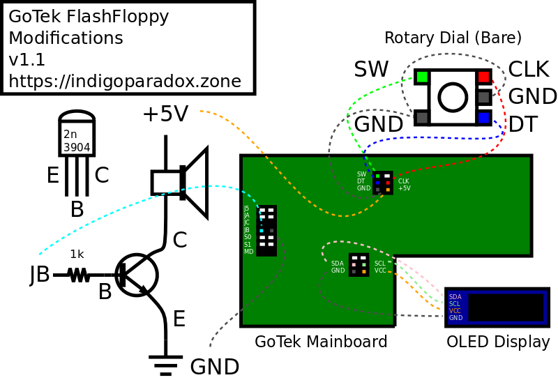
The information here applies to the current revision of the Gotek floppy emulator as of this writing, using the Artery microcontroller and with the jogdial header present... older revisions do not have the jogdial header and newer revisions may have other issues. Make sure the headers in the diagram below are available! Check the wiki if in doubt!
Please note that it may be advisable to flash the firmware first, as plugging in the USB cable for that may cause the speaker to emit a constant, irritating screech until firmware is flashed. These modifications REQUIRE the FlashFloppy firmware to be used!
2 - 1. Bill of Materials
- Electronic Buzzer
- OLED Display
- Rotary Dial
- 2n3904 NPN Transistor
- 1k Resistor
2 - 2. Diagram

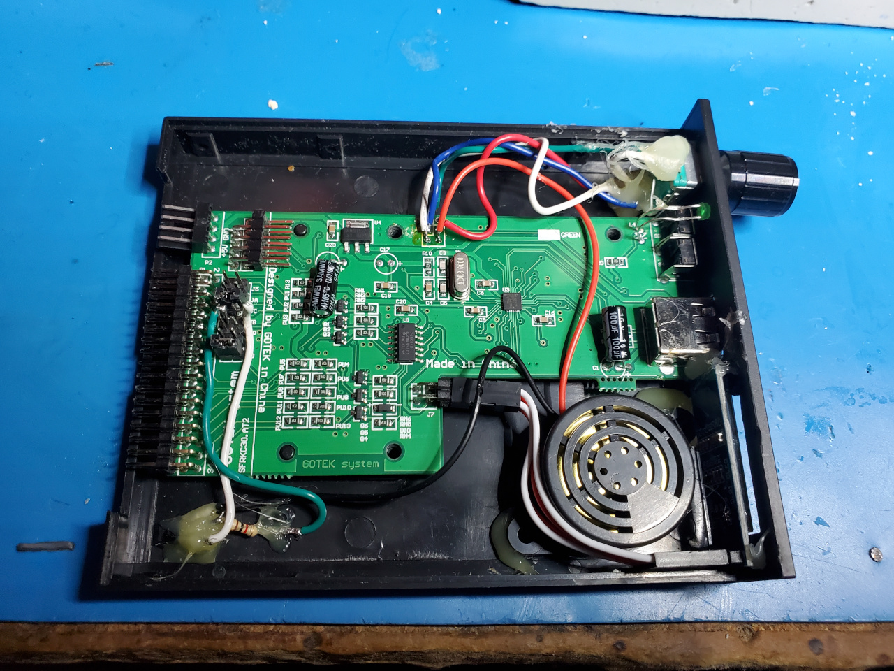
3. Photos


4. Flashing and Software
4 - 1. Firmware Flashing
This is fairly standard, according to the FlashFloppy Wiki. The script below will flash a Gotek connected via a double-A-ended USB cable and with the jumper wire installed as per the FlashFloppy wiki page.
If the firmware does not flash with this procedure, make sure you have the jumper wire installed and try running the script several times!
| 1 | #!/bin/sh |
| 2 | |
| 3 | DFU_FILE="$1" |
| 4 | |
| 5 | # First, run the unprotect command (needs -D, even tho it doesn't use the file). |
| 6 | # This will probably generate an error, but it's fine. |
| 7 | sudo dfu-util -s :unprotect:force -D $DFU_FILE -a 0 |
| 8 | |
| 9 | sleep 3 |
| 10 | |
| 11 | # Perform the actual flash. |
| 12 | sudo dfu-util -D $DFU_FILE -a 0 |
4 - 2. Companion Software
Once FlashFloppy is running, the OLED display should show the current version when power is applied. The vfloppy repository contains some scripts for working with floppy images from ZIP files and directories on the Linux command line via mtools.
5. Floppy Server
If your retrocomputer is connected to a KVM and stowed out of the way, you may also want to be able to change the floppy at a distance. This is doable using a Raspberry Pi Zero W connected to the USB port of the Gotek via USB-OTG.
5 - 1. Hardware
You will need a Raspberry Pi Zero W with appropriate power supply. You will also need a USB-A to Micro-USB-B cable with the power (usually red) wire disconnected! This is important! You can use a breakout board or just cut the cable and only rejoin the green, white, and black wires. But the red wire MUST be disconnected! We are not responsible for any damage that may occur as a result of failure to do this (or from anything else here, for that matter)!
Once you have these things:
- Connect the modified USB cable from the "USB" micro-USB port on the Pi to the USB port on your GoTek.
- Connect the power supply to the "Power" micro-USB port on the Pi.
5 - 2. Software
The Raspberry pi will presents a constructed "container" image which contains both a floppy image and an FF.CFG file which automatically loads that image to the Gotek via the USB-OTG layer.
The "container" image is assembled by a simple piece of software called floppcgi, which runs as a FastCGI daemon sitting behind nginx. This daemon then responds to web requests, presenting a web page for selecting the image to use.
This section assumes a standard installation of the current version of the Raspbian OS Lite image. It was tested with Buster, but hopefully future versions should work with minimal modification.
It is highly recommended to use the Raspberry Pi Imager utility to flash the imager, as this allows you to setup your wireless network without connecting a display and keyboard to your Raspberry Pi Zero.
- You have cloned the floppcgi repo to /opt/floppcgi.
- You have a collection of floppy disk images in /srv/Floppies.
The script below is simplified, to illustrate the steps to getting it working. It assumes running as root and lacks idempotence. A more robust setup.sh is included in the floppcgi repo.
| # Install required packages. | |
| apt install nginx libfcgi-dev mtools git | |
| # | |
| # Add dwc2 overlay for USB Gadget support. | |
| echo "dtoverlay=dwc2" >> /boot/firmware/config.txt | |
| # | |
| # Add dwc2 module for USB Gadget support. | |
| echo "dwc2" >> /etc/modules | |
| # | |
| # Copy the site config to nginx. | |
| cp floppcgi.nginx /etc/nginx/sites-available/floppcgi | |
| ln -s /etc/nginx/sites-available/floppcgi /etc/nginx/sites-enabled | |
| rm /etc/nginx/sites-enabled/default | |
| # | |
| # Add config variables to FastCGI environment. | |
| echo "fastcgi_param FLOPPIES_ROOT /srv/Floppies;" >> /etc/nginx/fastcgi.conf | |
| echo "fastcgi_param FLOPPIES_CONTAINER /tmp/floppyc.img;" >> /etc/nginx/fastcgi.conf | |
| echo "fastcgi_param FLOPPIES_ASSETS /opt/floppcgi;" >> /etc/nginx/fastcgi.conf | |
| # | |
| # Copy the floppcgi service to /etc/systemd/system. | |
| cp /opt/floppcgi/floppcgi.service /etc/systemd/system | |
| systemctl start floppcgi |
5 - 3. Recommendations
- Install the log2ram package to put log files in RAM and reduce wear on the SD card.
- Place /tmp on tmpfs to reduce wear on the SD card.